To use this site, please enable javascript
To use this site, please enable javascript
2019 marks the centenary of the Grand Scuttle of Scapa Flow, where Germany’s remaining WWI fleet of 74 warships intentionally sank itself off Scotland’s Orkney Islands to avoid handing over the High Seas fleet as part of the 1919 peace terms.
To construct a more accurate narrative of the day’s events, as well as the processes affecting these wrecks, the remaining wrecks of Scapa Flow have been multi-beam surveyed in 2017 assisted by EIVA NaviSuite software to survey and model the wrecks.
The findings have been recently released by Dr Innes McCartney in his book Scapa 1919: The Archaeology of a Scuttled Fleet. We are pleased to present a portion of the book’s introduction to give you a peek into the archaeological work EIVA NaviSuite was fortunate to be a part of.
The scuttle made headlines globally in June 1919, as the 74 most powerful vessels of the undefeated High Seas surface fleet interned at Scapa Flow made their way down into the waves on the orders of Admiral von Reuter.
Due to a fortunate series of circumstances, Admiral von Reuter managed to sink his fleet in the afternoon hours of 21 June 1919 upon learning the Versailles peace terms, a mere two days before the planned seizure of the fleet by the British. The Royal Navy attempted to stop the foundering of the ships and managed to beach 20 of the 50 torpedo boats but only managed to prevent the sinking of one battle ship and three light cruisers. Most of the vessels have been salvaged, leaving 9 surviving wrecks at Scapa. The wrecks of Scapa Flow have officially also become part of the UNESCO’s Underwater Cultural Heritage, as they have now been under water for 100 years, thus further increasing their significance.
In 2017, marine archaeologist Dr Innes McCartney of Bournemouth University joined the Sea War Museum Jutland again, on this occasion to compile this account of Scapa Flow, now published in the book ‘Scapa 1919: The Archaeology of a Scuttled Fleet’.
A meticulous survey was carried out on the 9 shipwrecks of Scapa – the 3 battleships SMS König, Markgraf, Kronprinz Wilhelm; the 4 light cruisers SMS Brummer, Karlsruhe, Cöln, Dresden and the 2 torpedo boats SMS S54 & V83 – to be compared with the 2006 ADUS multi-beam survey, utilising the unique opportunity to study the site formation processes that took place in the decade that passed.
Inserted below is an excerpt of the book's introduction, detailing the multi-beam survey data acquisition and post-processing which took place in EIVA NaviSuite, resulting in sophisticated 3D models of these historic legacies.
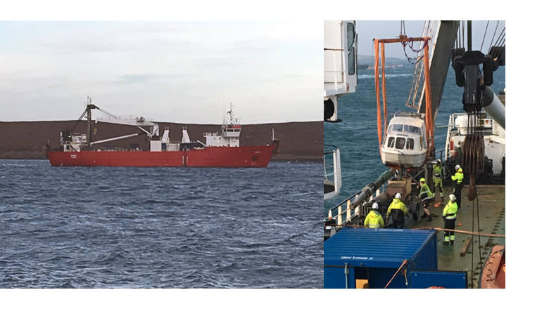
Figure iii. The Sea War Museum Jutland’s two survey vessels used to survey Scapa Flow in 2017. Left, MV Vina, and right, the Limbo being deployed from Vina during the survey.
by Dr Innes McCartney
The Sea War Museum Jutland carried out a multibeam survey of Scapa Flow over a 10-day period in January 2017. As the museum’s affiliated archaeologist, I was present throughout and was involved in the planning of the project and the subsequent processing and presentation of all of the multibeam data shown in this book.
Due to their relatively shallow depth, the nine remaining wrecks are ideal shipwreck targets for a multibeam survey. Aside from the wrecks, we also wanted to use the multibeam to search and map as much of the former German anchorage, as well as the salvage areas around it, as we could in the time allocated. We also wanted to scan a number of other very shallow areas. To acquire the data needed we employed two survey vessels: the 2,065-tonne survey ship Vina, our base of operations, and Limbo, a small day boat which can operate in very shallow water.
Both vessels are equipped with identical Reson 7125 multibeam systems and they use EIVA Navisuite software. The two vessels can be seen in Figure iii. As it was, Limbo proved exceptionally useful because a number of areas were simply too shallow or enclosed for Vina to work in. Full credit goes to the team who worked on Limbo every day in sometimes choppy conditions. It was not a task for those who get seasick. The data Limbo gathered on the shallow sites, such as SMS S36, are unrivalled in detail.
The survey ended up covering an area of around 40km2. The data were readied for archaeological analysis as shown in Figure iv, with the greatest care being taken to acquire the highest resolution possible on each specific shipwreck site.
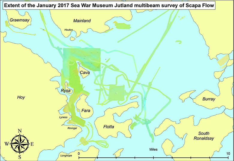
Figure iv. The full extent of the area of coverage of the 2017 multibeam survey. The focus was on the German
anchorage, but all the other major shipwrecks were also scanned.
Multibeam systems create a sound pulse in a fan of up to 512 individual beams from an echosounder under the hull. The returning soundwave is picked by an antenna array and the directional information is processed to produce a swath of depth readings in three dimensions. Multibeam is primarily used by hydrographic surveyors to acquire data relating to depth of water and type of seabed. Its ability to record objects on the seabed in three dimensions makes it a useful tool for surveying shipwrecks. This is particularly the case when the wrecks are very large or when there is low visibility or marine growth that make surveys by more traditional diving methods challenging.
The shipwreck survey data we acquired came in the form of a point cloud, made up of millions of individual depth readings. A point cloud can be processed in several different ways to maximize its potential archaeological value. The means by which the shipwreck data from the Scapa survey were processed is given in Figure v, which uses the example of the battleship wreck of SMS Markgraf.
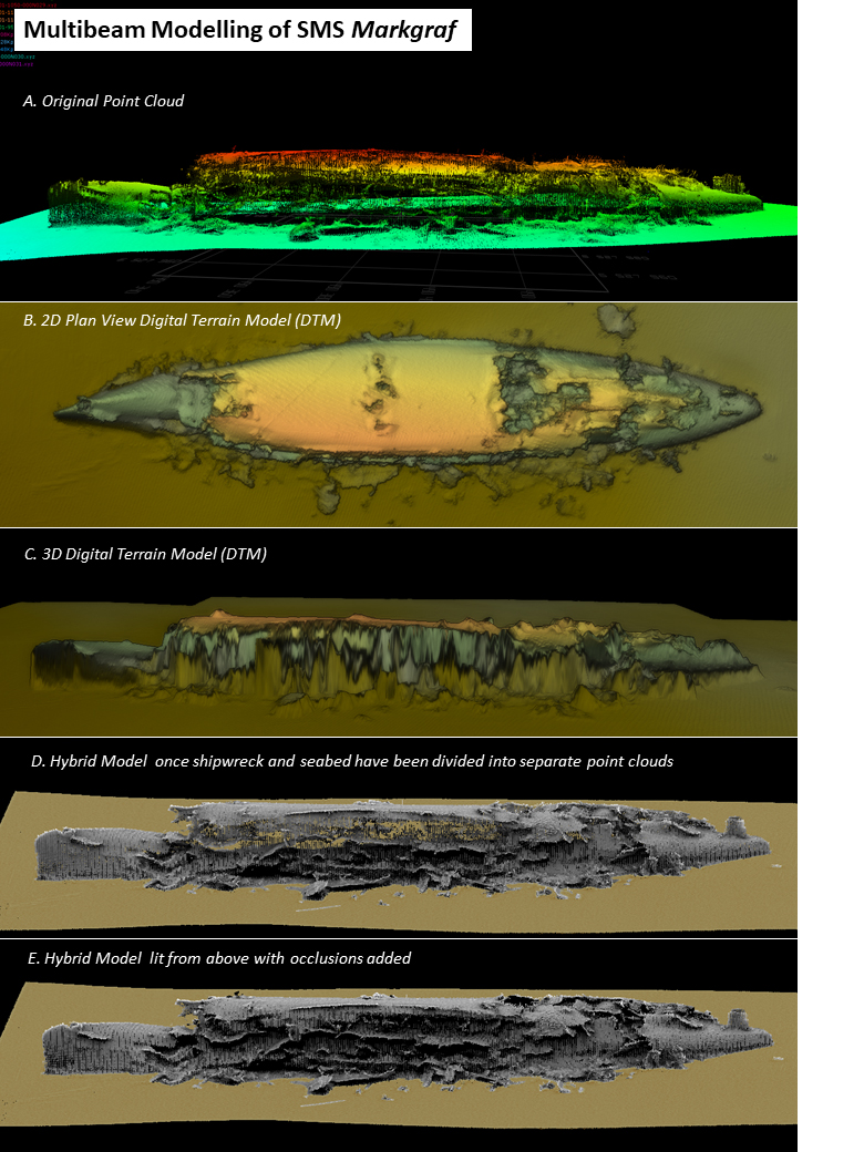
Figure v. The original point cloud gathered over SMS Markgraf and how it was processed to produce the
survey results.
Starting at the top, Image A shows the original point cloud once it is drawn out from the original survey data. It has been coloured to give height readings from the seabed. It shows every depth point recorded over the entire shipwreck. The challenge for surveyors on objects which stand up off the seabed, such as this, is to get point readings from the vertical aspects of the object. In a hull-mounted multibeam system, the ‘top-down’ nature of the soundings means that points generally accumulate on horizontal surfaces, as can be clearly seen.
In Image B the point cloud has been processed into a ‘Digital Terrain Model’ (DTM), shown from above in plan view and coloured to show height range. The DTM plan view is usually used for seabed mapping, and it creates excellent site maps which are used to depict every wreck site. Accurate measurements can be made from them and, as with all the data, it can be georeferenced into the maps of the survey. Its limitations are evident when covering larger upstanding objects, when a curtaining effect is seen in three dimensions, as shown in Image C.
In order to avoid this effect and study the wreck in three dimensions the point cloud is processed in another way to create a ‘hybrid model’. The point cloud is manually cut into sections which separate the seabed from the wreckage. These separate point clouds are then coloured differently. In Image D the initial result is shown, with artificial ‘illumination’ from directly above. This is suitable for most applications, but in the case of large solid objects the absence of points on some vertical surfaces creates the false impression that the wreck is see-through and hollow inside.
Finally, to give a more accurate visual impression, occlusion objects are added to the interior of the point cloud. The final solid-looking model can be seen in Image E. I first came across the use of occlusion objects in the 2006 ADUS survey of the wrecks, which produced excellent results. Our hybrid models were prepared in the same way in order to analyse how the wrecks have deteriorated in the 11 years between surveys. Image E clearly shows how the edges of decks can be seen poking out of the side of the wreck from areas where the original outer armour of the ship has been removed by salvage.
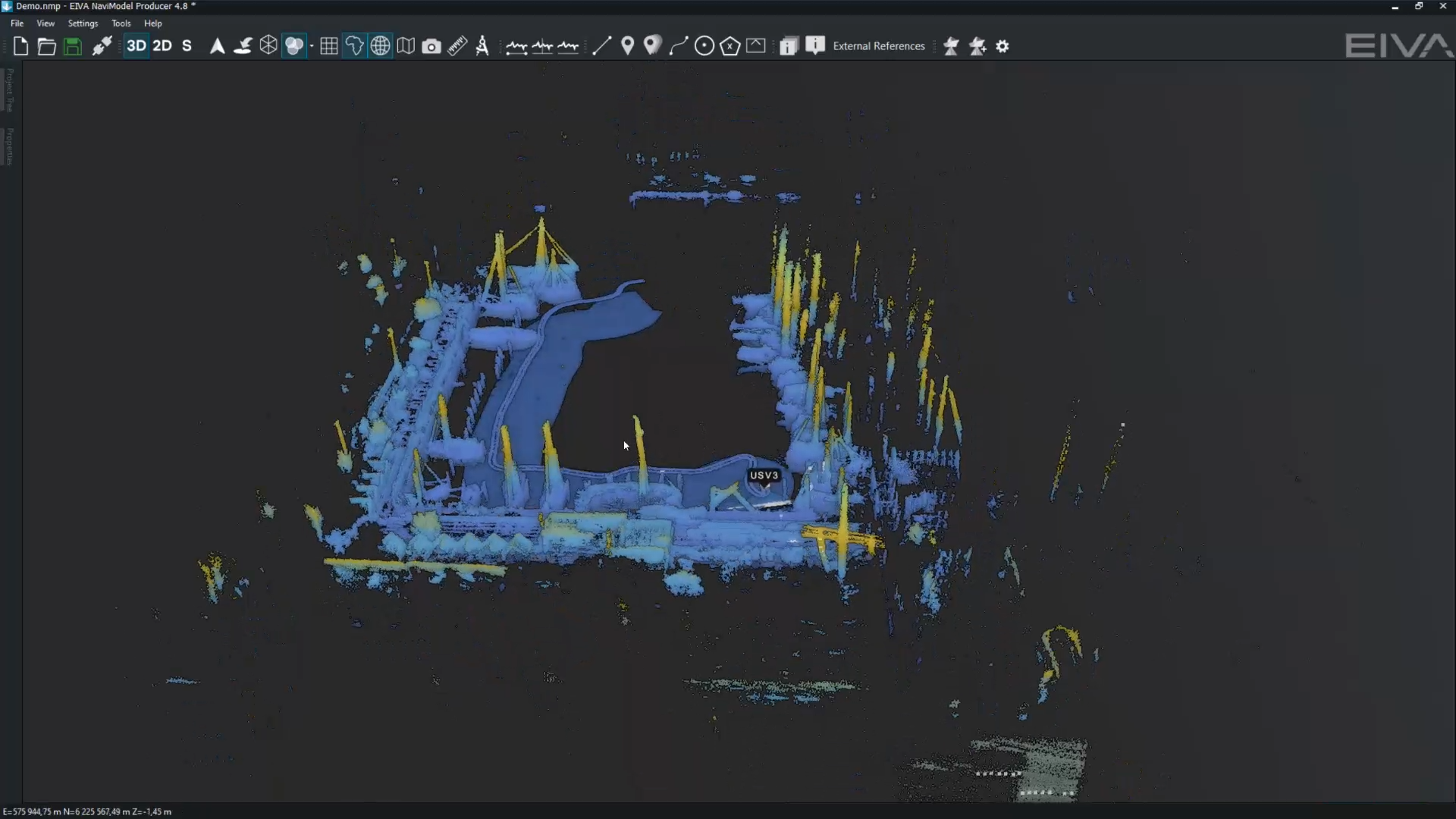
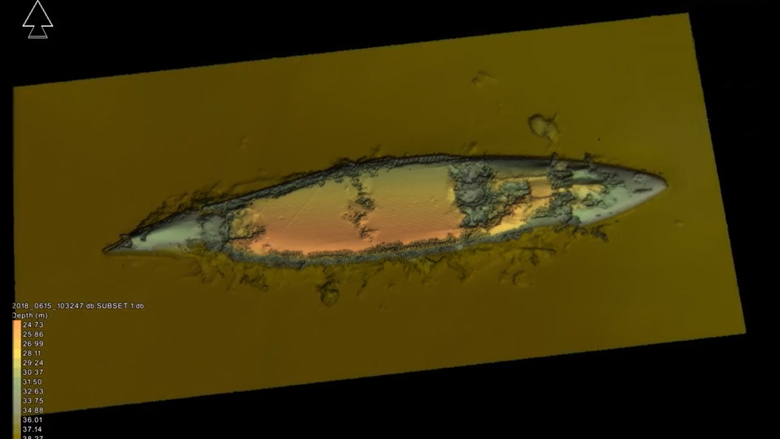
3D multibeam model of SMS Cöln, made for 'Scapa 1919: The Archaeology of a Scuttled Fleet'.
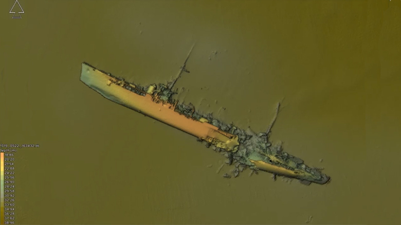
SMS Markgraf multibeam model. Made for 'Scapa 1919: The Archaeology of a Scuttled Fleet' from survey data gathered in 2017.
‘Scapa 1919: The Archaeology of a Scuttled Fleet’ is available on Amazon.com, Osprey Publishing and other domains.