To use this site, please enable javascript
To use this site, please enable javascript
Author: EIVA Global Product Sales Manager Henrik Østergaard Fjendbo
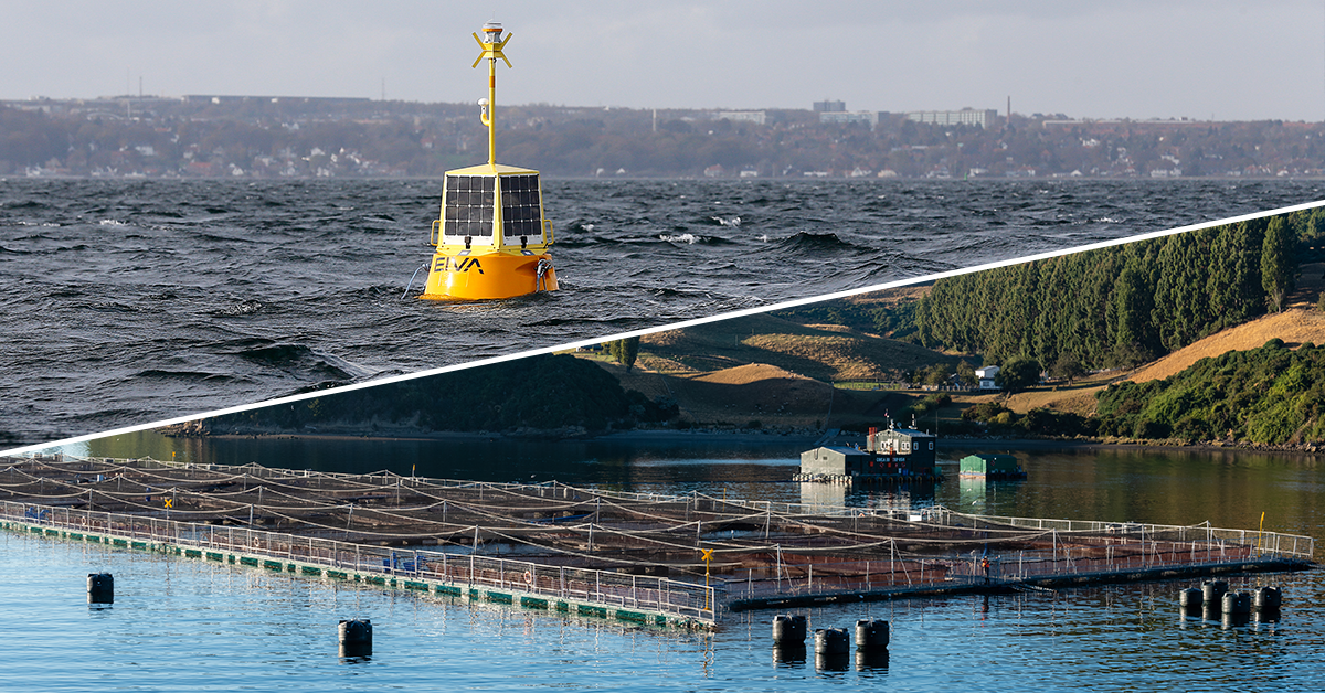
When using a data buoy on offshore construction or survey projects, it’s important to keep operation costs at a minimum. A key element in this is ensuring that the buoy is operational as long as possible by prolonging the intervals between maintenance and, of course, changing the battery.
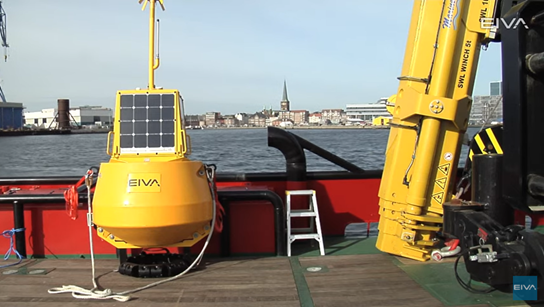
The EIVA ToughBoy Panchax data buoy solution was released in 2014. It concluded a design process which, among others, was based on the requirement that the wave buoy had to have (and produce itself) enough power to be operational for a minimum of 12 months between battery change under conditions similar to those found in the North Sea, where there is far less sun energy to harvest than in areas closer to equator.
During the design process, it proved necessary to work on minimising the magnetic disturbance caused by the alkaline battery packet. This was achieved with a five-time reduction of the magnetic field, resulting in far greater precision of the sensor data.
The 12-month requirement stretches the limits of more traditional ways of working with the power consumption of buoys. Nevertheless, by bringing the synergies and capacity of two different battery types into play in the design process of an intelligent power handling system it became possible to meet the requirement.
The power system has two sections, a primary energy source and a secondary energy source. The primary source consists of four 50-W solar panels, a deep-cycle 1,200 Wh AGM battery, and two MPPT (Maximum Power Point Tracking) charge controllers. The secondary source is a 16,000-Wh custom-assembled alkaline battery packet. The two energy sources are combined by the intelligent power handling system (IPHS).
Whenever the primary energy source is able to contribute with sufficient power to the buoy’s sensor data collection and processing system, the IPHS will give priority to it. During periods where power harvested from the solar panels is limited by a low amount of sun hours, such as during the winter season in the North Sea, the secondary battery will step in.
For example, if the buoy is deployed close to the equator where the annual number of sun hours are evenly distributed over the year, the data buoy will be able to run on the primary energy source alone. In situations like these, the secondary energy source only functions as a backup, which will allow the buoy system to surpass the 12-month requirement in terms of battery change.
The MPPT charge controllers allow the primary battery to be charged by the solar panels. Moreover, it ensures that the primary battery is disconnected if the voltage becomes lower than 10.8 V DC – and back on when it is higher than 12.5 V DC. At the same time, the IPHS will activate/deactivate the secondary battery via a custom high-speed MOSFET switching circuit, designed with fast switching ability, power source shortage protection, and low idle power. This prevents power dropout and power source shortage, ensuring that the data collection carried out by the sensors on the buoy is not interrupted.
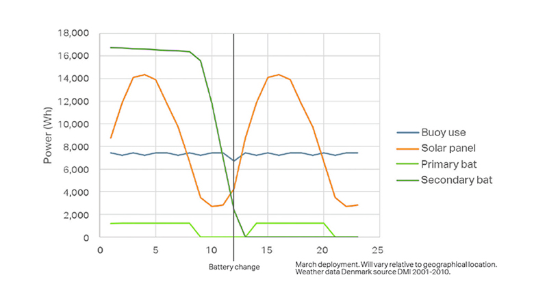
Power budgets in months with deployment in March – graph will vary relative to geographical location
The encapsulation of the custom-designed alkaline battery packet is made with safety and sturdiness in mind. The alkaline cells are divided into four sub-banks for better stability and immunity against vibrations of the 100-kg battery cells. The four sub-banks are electrically combined into two larger banks which are electrically isolated to minimise the risk of a damaged cell destroying the whole package. Both the primary and secondary battery are wrapped in vibration damping foam and mounted in a sealed stainless steel box.
An alkaline battery/cell consists of ferromagnetic material, which means it is surrounded by a small magnetic field. There are 560 pieces D/LR20 alkaline cells in the secondary battery packet. This results in a multi-fold amplification of that small magnetic field, up to 5-7 times the earth’s magnetic field (~55 uT in Denmark, where EIVA is headquartered), measured at a distance of 0.5 metres.
A too-high magnetic disturbance would affect the precision of the heading sensor of the buoy. Consequently, various battery configurations were tested during the design phase to reduce the magnetic field.
We ended up with a 5-time reduction of the total field and 8-time reduction of the magnetic field radiated in the top of the packet. This was ensured via a configuration in which the magnetic fields of the individual cells cancel each other out.
The battery configuration with the worst result (Figure 2 and Figure 3) had a total magnetic field of ~2000 uT measured over 64 points in a special made test cradle. The top field was measured to ~850 uT over 16 points. The best configuration (Figure 4 and Figure 5) had a total magnetic field of ~350 uT and magnetic top field of ~90 uT.
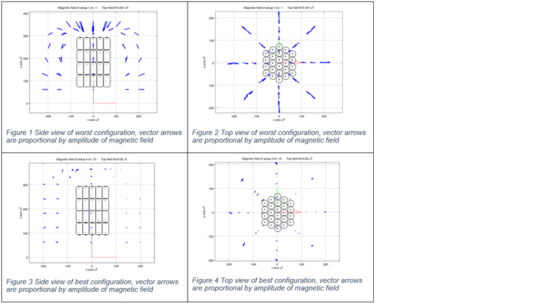
Side and top views of the worst and best battery configurations for the Toughboy wave buoy with vector arrows
A further reduction of the magnetic field can be performed by demagnetising the battery packet. However, due to the positive effect of the above configuration (Figures 4 and 5), this is not necessary for the setup in the ToughBoy Panchax. Moreover, all produced battery packets’ magnetic fields are measured to ensure they are below acceptable values.
We already have an additional, larger version of the buoy making its way from the drawing board to our warehouses. The existing solution has a diameter of 1.2 metres, but we are now designing a 1.8-metre version for deployment in deeper waters and with a generic sensor driver – that is, the possibility of adding even more sensors to the buoy setup for current and wave measurement surveys.
This will bring new requirements to the power system, and hence a necessity of looking into for example the capacity of the solar panels and the batteries.
Other interesting technologies to look into in the future could be to ensure power from other energy sources such as wave energy and fuel cells.